SURFACE FORCES AND CAPILLARY PRESSURE
Surface forces and capilliary pressure
Surface Tension and Interfacial Tensions
In dealing with multiphase systems, it is necessary to consider the effect of the forces acting at the interface when two immiscible fluids are in contact. When these two fluids are liquid and gas, the term "surface tension" is used to describe the forces acting on the interface. When the interface is between two liquids, the acting forces are called interfacial tensions.
Consider the two immiscible fluids, air (or gas), and water (or oil), as shown schematically in Figure.7-1 A liquid molecule, which is remote from the interface, is surrounded by other liquid molecules, thus having a resulting net attractive force on the molecule of zero. A molecule at the interface, however, has a force acting on it from the air (gas) molecules lying immediately above the interface and from liquid molecules lying below the interface.
Resulting forces are unbalanced and give rise to surface tension. The unbalanced attraction force between the molecules creates a membrane like surface with a measurable tension, i.e., surface tension. As a matter.
") |
Figure. 7-1
Illustration pf surface tension (after Clark, N.J, Element of
|
Petroleum
Reservoir, SPE, 1969) |
A certain amount of work is required to move a water molecule from within the body of the liquid through the interface. This is frequently referred to as the free surface energy of the liquid. Free surface energy, measured in ergs per square centimeter, may be defined as the work necessary to create a unit area of a new surface. Interfacial tension and surface tension are commonly expressed in ergs per square centimeter.
In dealing with hydrocarbon systems, it is necessary to consider not only the interface between a gas and a liquid but also the forces that are active at the interface between two immiscible liquid phases and between the liquids and solids.
Evaluation:
Interfacial tension can be evaluated using the Young -Dupree equation. The equation is
Where Ϭso is Surface tension between oil and the solid surface, [dynes/cm], Ϭsw is Surface tension between water and the solid surface, [dynes/cm], Ϭwo is interfacial tension between oil and water, [dynes/cm] and cos ϴ is angle at (oil-water) - solid interface measured through the water.
Adhesion Tension
The adhesion tension, which is a function of the interfacial tension, determines which fluid will preferentially wet the solid.
the adhesion tension AT is defined as
positive adhesion tension (AT) indicates that water preferentially wets the solid surface (water is wet). An (AT) of zero indicates that both phases have an equal affinity for the surface (neutral system). A negative (AT) indicates the oil wets the solid surface (oil wet). The magnitude of the adhesion tension determines the ability of the wetting phase to adhere to the solid and spread over its surface.

Rise of Fluid in Capillaries
Take the example of capillary tubes, which have a very small internal tube diameter. Water will rise in the capillary tube above the level of the water in the larger open vessel if the tube is positioned as shown in Figure 7.3. This increase in height results from: The attractive forces (adhesion tension) between the tube and the liquid.
1. Wettability of tube to water.
2. The small weight represented by the column of liquid in the tube.
The adhesion tension is the force tending to pull the liquid up the wall of the tube. The water will rise in the tube until the total force acting to pull the liquid upward is balanced by the weight of the column of liquid being supported in the tube.
 |
Figure. 7.3 Pressure relations in
capillary tubes |
The well-known expression for liquid surface tension is obtained by equating the upward and downward forces on the elevated column.
Force up=
Where r is radius of capillary tube, Ϭgw is surface tension between air (gas) and water [dynes/cm], ϴ is contact angle of the system, h is height of the column, ρw is density of water, [gm/cm3], ρair is density of air, [gm/cm3], and g is gravitational constant.
Because the density of air is negligible in comparison with the density of water, equation is reduced to:

Capillary Pressure
Capillary pressure (Pc) can be defined as:
- The pressure necessary to displace a wetting fluid from a capillary opening.
- The pressure difference across a curved interface between immiscible fluids, one of which wets the surface of the rock in preference to the other.
- Petroleum engineering convention defines capillary pressure as the pressure in the oil phase minus the pressure in the water phase. In an oil wet system, the value can be negative.
where, Pnwt is pressure of the nonwetting phase, Pwt is pressure of the wetting phase.
For an oil/water system in porous rock, Pc is generally defined as the pressure difference between the oil phase (Po) and water phase (Pw), i.e.
Referring to Figure 7.3 the pressure difference across the interface between point 1 and 2 is essentially the capillary pressure, i.e.:
The pressure of the water phase at point 2 is equal to:
Where is the pressure in the water at the top of water column, is the pressure in the water at the bottom of column, and pressure due to a head of water h.
The pressure just above the interface at point 1 is equal to:
Where p1 and p3 are the pressure in the gas at both the top and bottom, and pressure due to a head of air.
Since the beaker is large compared with the capillary tube, the gas-water interface in the beaker is essentially horizontal. Because capillary pressure is zero at a horizontal or plane interface,
p3=p4
Subtracting equation gives:
The head of air is negligible. Therefore, the pressure in the air immediately above the interface is essentially equal to the pressure in the air immediately above the free water level in the large vessel.
where ρc is density of water, h is height of the column of water the tube above that in the large vessel.
By balancing the upward and downward forces

since

substituting the above value for the height in equation to give the expression

This expression for capillary pressure in term of the surface forces for gas-water system.
θ_wo = the water-oil interfacial tension.
For oil-water system


Where Pc is capillary pressure, ∆ρ is density difference between the wetting and non-wetting phase, [lb/ft3], and h is height above the free water level.
Factor which govern capillary pressure:
1. Surface or interfacial tension of the fluid involved.
2. The system wettability. The greater the affinity of the denser phase for the solid. The greater will be the Pc.
3. The size (radius) of the capillary. The smaller the radius when the wetting characteristics are the same, the greater will be the Pc.
Laboratory measurement of capillary pressure
Porous diaphragm
Porous diaphragm: desaturation or displacement process through a porous diaphragm of membrane (restored state method). The diaphragm method is illustrated in Figure.7.4.
 |
Figure. 7.4
Diaphragm method |
Procedure:
1- A reservoir core of known pore volume is saturated 100 % with water and placed in contact with the wet membrane, which is also saturated 100% with water. The membrane has extremely small pores and will not allow a non-wetting fluid to enter it at the pressures to be used in the test.
2- a non-wetting fluid (oil, air, nitrogen, etc.) is then introduced into the cell at slightly elevated pressure.
3- The air (or non-wetting fluid) will enter all the pores in the core sample with a capillary pressure less than that applied.
4- The water displaced from the core is forced through the membrane and collected in a suitable container.
5-The displaced water volume is recorded when it becomes constant at a given pressure.
The saturation may be computed by weighing at the particular pressure.
6-This procedure is repeated in subsequent, higher pressure steps until an increase in pressure forces no more water from the core (irreducible value).
The resultant plot of capillary pressure versus saturation is shown in Figure 7.5
 |
Figure. 7.5
Capillary pressure curve |
1) The minimum pressure which will
displace water from the largest pore is called the displacement or entrance
pressure.
2) any immiscible displacement
process is encountered, that is the reaching of some finite minimum irreducible
saturation. This irreducible water saturation is referred to as connate water.
Advantages:
1. most accurate
and widely used.
2. The multiple
samples can be tested simultaneously.
3. applicable to a
variety of sample sizes and permeability ranges.
Disadvantage:
1. Time required
to carry out this technique: several days may be required to reach a
satisfactory equilibrium at each step.
2. The method is
usually not used for unconsolidated samples due to difficulties in obtaining
capillary contact with the plate, the potential for excessive grain loss, and
the lack of confining pressure on the sample.
3. pressure
investigation's limitations
Mercury Injection
This is similar in principle to the
restored state method. The mercury capillary pressure apparatus is shown in Figure
7.6.
1.
The core sample is washed, dried, first inserted in the mercury
chamber, and then evacuated.
2.
Mercury is forced into the core under increasing pressure.
3.
The volume of mercury injected at each pressure determines the
non-wetting phase saturation.
4.
This procedure is continued until the core sample is filled with
mercury or the injection pressure reaches some predetermined value.
5.
The pore volume is determined beforehand.
6.
The capillary pressure is the absolute pressure of the mercury.
7.
A curve of capillary pressure versus mercury saturation is thus
obtained.
Advantages:
1-The time for determination is
reduced to a few minutes.
2- The range of pressure
investigation is increased as the limitation of the properties of the diaphragm
is removed.
 |
Figure.
7.6 Apparatus for mercury injection method. |
Disadvantage:
The difference in wetting properties and permanent loss of the core sample since it is destructive method.
Centrifuge Method
A third method for determination of capillary properties of reservoir rocks is the centrifuge method illustrated in Figure 7.7.
The high accelerations in the centrifuge increase the field of force on the fluids, subjecting the core, in effect, to an increased gravitational force.
- When the sample is rotated at various constant speeds, a complete capillary pressure curve can be obtained.
- The speed of rotation is converted into force units in the center of the core sample, and the amount of fluid removed is read visually by the operator.
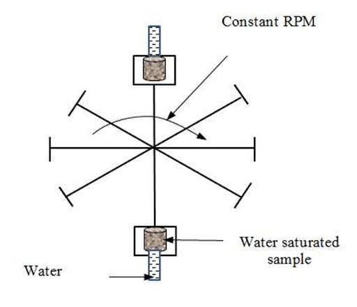 |
Figure. 7.7
Measurements of capillary pressure curves by centrifuge method |
Advantages:
1- Increased speed of obtaining the data.
2- A complete curve can be established in a few hours, while thediaphragm method requires days.
3- Non-destructive.
Disadvantages:
1- Data interpretation is more complex, and numerical simulation may be required.
2- It is difficult to account for the increase in speed of reaching equilibrium as compared with the diaphragm method since the same resisting forces appear to be involved in the core.
If the brine saturated sample with density ρ1 is placed in a centrifuge rotating at n RPM. The sample is located within a medium with the specific gravity ρ2 (air or oil). The maximum pressure difference on the end face of the core is given by the equation.
where ∆p is the pressure difference on the end face, h is centrifuge plate radius, γ is constant depending upon instrument, and A is constant depending upon units.
Capillary Hysteresis
It is generally agreed that the pore spaces of reservoir rocks were originally filled with water, after which oil moved into the reservoir, displacing some of the water and reducing the water to some residual saturation. When discovered, the reservoir's pore spaces are filled with a connate water and oil saturation. All laboratory experiments are designed to duplicate the saturation history of the reservoir. The process of generating the capillary pressure curve by displacing the wetting phase, i.e., water, with the nonwetting phase (such as with gas or oil) is called the drainage process.This drainage process establishes the fluid saturations that are found when the reservoir is covered. The other principal flow process of interest involves reversing the drainage process by displacing the nonwetting phase (such as oil) with the wetting phase (e.g., water).
This displacing process is termed the imbibition process, and the resulting curve is termed the capillary pressure imbibition curve. The process of saturating and desaturating a core during the nonwetting phase is called capillary hysteresis. Figure 7.8 shows typical drainage and imbibition capillary pressure curves. The two capillary pressure saturation curves are not the same. This difference in the saturating and desaturating of the capillary-pressure curves is closely related to the fact that the advancing and receding contact angles of fluid interfaces on solids are different.
Frequently, in natural crude oil-brine systems, the contact angle or wettability may change with time. Thus, if a rock sample that has been thoroughly cleaned with volatile solvents is exposed to crude oil for a period of time, it will behave as though it were oil-wet. But if it is exposed to brine after cleaning, it will appear wet. At the present time, one of the greatest unsolved problems in the petroleum industry is that of the wettability of reservoir rock.

Converting laboratory data:
To use laboratory capillary-pressure data, it is necessary to convert to reservoir conditions. Laboratory data are obtained with a gas-water or an oil-water system, which does not normally have the same physical properties as the reservoir water, oil, or gas. As shown previously, by means of the capillary tube, the capillary pressure is expressed as

Considering a specific case where in the laboratory values are determined with gas and water, the capillary pressure becomes

Where σ_wg is the interfacial tension between gas and water used in laboratory test, r is the radius of the capillary.
The capillary pressure which would exist if reservoir fluids, oil and water,
were used in the same capillary would be

where σ_wois interfacial tension between reservoir water and oil at reservoir temperature and pressure, θ_wois contact angle for reservoir water and oil, and r is radius of capillary.
Comparing the equations for laboratory and reservoir capillary pressure, it is found that the reservoir capillary pressure is

Thus, the reservoir capillary pressure can be calculated from the laboratory capillary pressure when the interfacial tension and contact angle between oil and water in the reservoir and gas and water in the laboratory are known.
1) It is possible from the capillary pressure curve to calculate the average size of the pores making up state fraction of total pore space.

2) for r providing that the interfacial tension Ϭ, and the angle of contact ϴ may be evaluated.
3) Fluid distribution in a reservoir prior to its exploitation. The capillary pressure saturation data can be converted into height-saturation data for the height h above the free water level.


Comments